


Raum: PB-A 107
 +49 271 740-2174
 heck@bau.uni-siegen.de
Influence of the method of filling the beam moulds on the homogeneity of fibre distribution and orientation and on the reproducibility of the results of three-point bending tests on ultra-high performance fibre reinforced concrete (UHPFRC)
Research topic
Design and construction with ultra-high performance concrete (UHPC)
Funding and project duration
German Committee for Structural Concrete (Deutscher Ausschuss für Stahlbeton, DAfStb), Research Project V 507
Duration: January 2020 until August 2021
Persons in charge
Lennart Heck, M.Sc.
Maximilian Schleiting, M.Sc. (Universität Kassel, Fachgebiet Werkstoffe des Bauwesens und Bauchemie)
Project partner
Universität Kassel
Werkstoffe des Bauwesens und Bauchemie
Prof. Dr. rer. nat. Bernhard Middendorf
Mönchebergstraße 7
34125 Kassel
Objectives
In practice, ultra-high performance fibre reinforced concrete (UHPFRC) is usually processed flowable to very flowable. The draft of the DAfStb Guideline "Ultra-High-Performance Concrete" provides for this case that the beams on which the residual flexural strength of UHPFRC is determined in three-point bending tests acc. to DIN EN 14651 are produced by filling the moulds from one end face. Earlier investigations of the fibre orientation and distribution had suggested that a characteristically heterogeneous fibre orientation occurs in the cross-section of the beams produced in this way. This raised the question of whether filling the mould from one end face can guarantee reliable and reproducible results.
Research Project V 507 therefore aimed to investigate the effects of different methods of filling the mould with regard to the homogeneity of the fibre orientation. Furthermore, it was to be determined to what extent a modified procedure affects the residual bending tensile strength as an essential performance characteristic of UHPFRC.
Experimental investigations
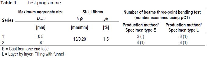
The test programme comprised two series of 6 beams with b/h/l = 150 mm/150 mm/550 mm made of UHPFRC. The steel fibres were 13 mm long and had a diameter of approx. 0.20 mm. The fibre volume fraction was 1.5 % in both series. The maximum aggregate size (Dmax = 0.5 mm and 8 mm) and the production method of the beams were varied.
Three beams of each series were cast acc. to the method currently provided in the draft of the DAfStb Guideline "Ultra-High-Performance Concrete" (filling from one end face of the beam mould, specimen type E). For the remaining three beams, the mould was filled in approx. 6 layers using a funnel with a rectangular outlet (specimen type L). For this purpose, the funnel was held about 1 cm above the already filled concrete and moved from one side to the other at the flow rate of the concrete. Table 1 gives an overview of the test programme.
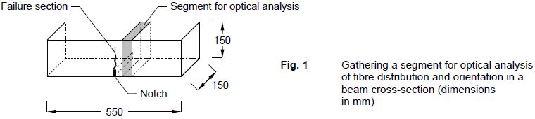
All 12 beams were tested in three-point bending tests acc. to DIN EN 14651. Afterwards, an approx. 50 mm thick segment was sawn out of the undamaged area of each beam close to the cross-section where the bending failure had occurred (Fig. 1), and the fibre distribution and orientation were opto-analytically examined using the analysis software FiDiOr.
Three of the 12 segments were also analysed using micro-computed tomography (µCT). With this method, the position and orientation of each individual fibre within a specimen volume can be visualised and defined in terms of geometry.
Test evaluation
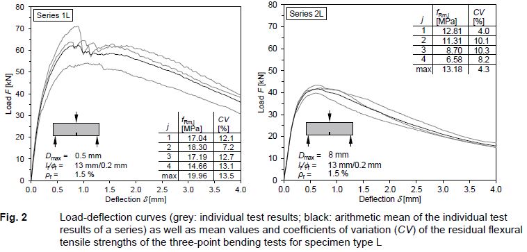
The three-point bending tests were evaluated by means of load-deflection curves, as exemplified in Fig. 2 for test specimen type L. The data was used to calculate residual flexural tensile strengths acc. to Eq. (1) for the midspan deflections δ1 = 0.47 mm, δ2 = 1.32 mm, δ3 = 2.17 mm, and δ4 = 3.02 mm as well as for the maximum of the load-deflection curve.
![]()
In Eq. (1), Fj is the load recorded in the test at midspan deflection δj in N, l is the span length of the beam in mm, b is the width of the specimen in mm, and hsp is the distance between the tip of the notch and the top of the specimen in mm.
From the data of the opto-analytical examinations and the examinations using µCT, the number of fibres nf, the mean fibre orientation coefficient of the volume ηV acc. to Eq. (2), and the "effective" fibre volume fraction ρf,ef acc. to Eq. (3) were determined for the cross-sections of the beams as well as for different sections of the reconstructed volume of the segments investigated by µCT.
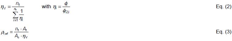
In Eq. (2) and Eq. (3), nf is the number of detected fibres in the evaluated area, ηi is the fibre orientation coefficient of fibre i, Φf is the nominal fibre diameter, Φf2,i is the length of the major axis of the elliptic section of the fibre i, Af is the area of the fibre cross-section and Ac is the evaluated area of the concrete cross-section.
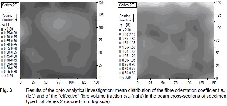
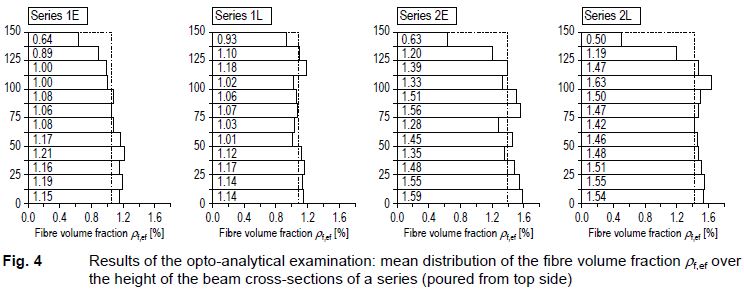
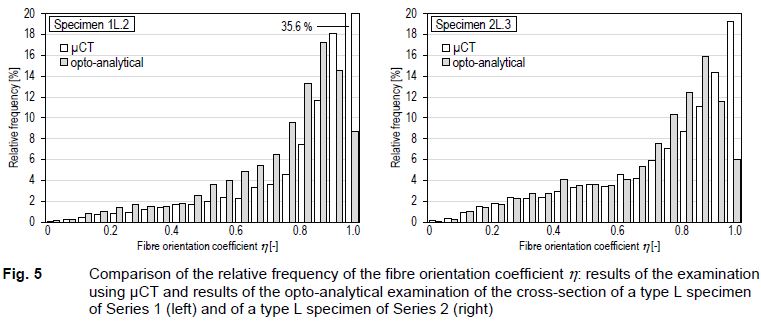
The distribution of the fibre orientation coefficient ηV and of the "effective" fibre volume fraction ρf,ef within a section was visualised by means of contour diagrams, as exemplified in Fig. 3 for specimen type E of Series 2. Furthermore, the mean distribution of the "effective" fibre volume fraction over the height of the beam cross-sections (Fig. 4) as well as the relative frequency of the fibre orientation coefficient was evaluated. Figure 5 compares for two specimens the distributions of the relative frequency of the fibre orientation coefficient η in a section obtained by means of µCT examination and opto-analytical examination.
Summary of the results and conclusions
In the three-point bending tests, differences in the load-deformation behaviour were found, which can primarily be attributed to the influence of the maximum aggregate size. The fine-grained UHPFRC showed higher residual flexural strengths than the coarse-grained UHPFRC (Fig. 2). The midspan deflection at ultimate load was larger for the fine-grained UHPFRC. In contrast, the softening branch of the coarse-grained UHPFRC was steeper than for the fine-grained UHPFRC. Due to the more unsteady course of the load-deflection curves, the coefficients of variation for the fine-grained UHPFRC were mostly well above the values for the coarse-grained UHPFRC. With regard to a possible influence of the production method, however, the results of the three-point bending tests did not reveal a clear trend. When relating the residual flexural tensile strengths to the fibre volume fraction active in tensile direction in the beam cross-section, the beams fabricated with the same maximum aggregate size show comparable performance or the differences are within the natural scatter range.
The opto-analytically determined parameters of the beam cross-sections (number of fibres nf, mean fibre orientation coefficient ηV, "effective" fibre volume fraction ρf,ef) as well as their scatter could not be related to the production method of the beams. However, an obvious influence of the maximum aggregate size could be observed with these values, too. For the fine-grained UHPFRC, higher mean fibre orientation coefficients η were found than for the coarse-grained UHPFRC, as well as by trend a larger scatter for all three parameters. For the coarse-grained UHPFRC, the distribution of the relative frequency of the fibre orientation coefficient was closer to the result for a spatially random orientation of the fibres. For the fine-grained UHPFRC, the fibres were preferably oriented in the longitudinal direction of the beam (Fig. 5).
An effect of the production method on the fibre orientation could only be determined for the pouring direction, i. e. for the direction normal to the longitudinal axis of the beam. Here, the evaluation of the µCT examinations showed a significantly higher mean fibre orientation coefficient ηV for the beam produced in layers with the funnel than for the beam cast from one end face. However, a different fibre orientation normal to the longitudinal axis of the beam theoretically has no influence on the result of the three-point bending test. In fact, no such influence was found in the three-point bending tests.
A systematic heterogeneous distribution of the fibre orientation in the beam cross-section, as had been observed in earlier investigations, could be found neither for the beams produced in layers with the funnel nor for the beams cast from one end face. Indeed, the specimens produced in the present research project also showed a varying fibre orientation across the cross-section (Fig. 3, left), a correlation between the production method and the homogeneity of the beams could, however, not be derived from the data.
In general, a slight increase of the fibre volume fraction towards the bottom of the mould could be observed in most of the beam cross-sections (Fig. 4). The beams produced in layers with the funnel seemed to be slightly less affected by this phenomenon. By rotating the beams by 90° for the three-point bending test, the heterogeneity of the fibre distribution indicating sedimentation of the fibres is almost completely compensated. Effects of a locally different fibre volume fraction within the cross-section on the test results are therefore not to be expected.
The evaluation of the data from the µCT examination for different cross-sections within a specimen volume showed that the number of fibres nf and, thus, also the "effective" fibre volume fraction ρf,ef vary considerably in the longitudinal direction of the beam even at short distance. In this respect, the residual flexural tensile strengths obtained in the three-point bending tests can, strictly speaking, only be reliably correlated with the results of an optical analysis or µCT examination if the number of fibres and the "effective" fibre volume fraction are determined for the actual failure section and not for a cross-section close to the failure section.
In the majority of the analysed sections, an "effective" fibre volume fraction ρf,ef was determined – irrespective of the evaluation method – which was in part significantly below the nominal fibre volume fraction (Fig. 4). For the fine-grained UHPFRC, the most significant undercut was found with ρf,ef = 1.02 to 1.13 % (optical analysis) and ρf,ef = 0.85 to 1.03 % (data from µCT examination). The reason for this could not be determined. A considerable deviation from the nominal fibre volume fraction for individual series could already be determined in earlier investigations.
The comparison of the results of the opto-analytical examinations and the examinations using µCT showed an overall good agreement of both evaluation methods. Only for fibres which were oriented approximately normal to the considered section, the optical analysis yield slightly too low fibre orientation coefficients, since the cross-section of the fibre detected in a section is identified as more elliptical (Fig. 5). For the fine-grained UHPFRC, the mean fibre orientation coefficient ηV obtained by the two evaluation methods differed most clearly due to the high proportion of fibres oriented predominantly in the longitudinal direction of the beam. Apart from this, the results of the optical analysis and the µCT examination can be considered equally reliable.
In summary, the results of this study suggest that filling the beam mould from one end face and filling the beam mould in layers with a funnel provide equally reliable and reproducible results.
Since the elementary characteristics of the beams produced with both methods do not differ significantly, it is recommended for the sake of simplicity to retain the filling of the beam mould from one end face as currently provided by the draft of the DAfStb Guideline "Ultra-High-Performance Concrete" for flowable to very flowable consistency of the concrete and to dispense with the use of a funnel as an additional aid.
Publications
HECK, L.; SCHLEITING, M.; LEUTBECHER, T., 2024. Computertomografie versus Optoanalytik: Bestimmung der Faserverteilung und -orientierung in stahlfaserbewehrtem UHFB. Beton- und Stahlbetonbau. 119(10), 777-791. doi:10.1002/best.202400040
LEUTBECHER, T.; HECK, L.; SCHLEITING, M., 2022. Prüfung von UHFB nach DIN EN 14651 – Zum Einfluss der Probekörperherstellung auf die Prüfergebnisse. Beton- und Stahlbetonbau. 117(6), 410-421. doi:10.1002/best.202200027
Supporting Information: Data S1. Ergebnisse der optoanalytischen Untersuchung