

Raum: PB-A 108
 +49 271 740-4029
 metje@bau.uni-siegen.de
Strength independent design approach for beams reinforced with steel fibres and reinforcing steel
Research topic
Design and construction with ultra-high performance concrete (UHPC), Mechanics of fibre reinforced concrete (FRC)
Funding and project duration
German Committee for Structural Concrete (Deutscher Ausschuss für Stahlbeton, DAfStb), Research Project V 508
Duration: January 2021 until June 2023
Person in charge
Kevin Metje, M.Sc.
Lennart Heck, M.Sc.
Objectives
Determining the flexural strength of cross-sections reinforced with a combination of reinforcing bars and steel fibres requires enhancing the assumptions applicable to reinforced and prestressed concrete. To account for the load-bearing capacity of the fibres in the flexural crack, a stress-strain curve is derived from measured stress-crack opening or load-deflection curves. This stress-strain curve often is assumed to be independent of the section depth and the reinforcement configuration. However, with such an approach the mechanisms can be approximated only for a specific scope of application (e.g. certain fibre volume fraction, fibre geometry, section depth or crack width). Since the boundary conditions for different scopes of application (normal-strength steel fibre reinforced concrete, ultra-high performance fibre reinforced concrete) differ significantly, this inevitably means that mechanisms, which are basically identical ("Natura non facit saltus"), cannot yet be consistently represented by a unique verification method.
Therefore, the research project V 508 aims to establish a mechanically based engineering model that allows the design for bending with/without axial force of both exclusively fibre reinforced and mixed reinforced beams independent of the concrete strength. Thus, inconsistencies in previous approaches focusing on steel fibre reinforced concrete may be eliminated. The approach is derived using the example of ultra-high performance fibre reinforced concrete (UHPFRC), for which the combination of steel fibres and conventional reinforcing steel is common practice.
Verification method
The proposed verification method provides a stress block to take account of the load-bearing effect of the steel fibres in the flexural crack. The stress block represents the solidity of the stress-crack opening relationship and the position of the stress resultant with sufficient accuracy. It is considered for the evaluation of equilibrium conditions together with a linear design stress-strain relationship of UHPFRC in compression and the well-known stress-strain curves for reinforcing or prestressing steel (Fig. 1).
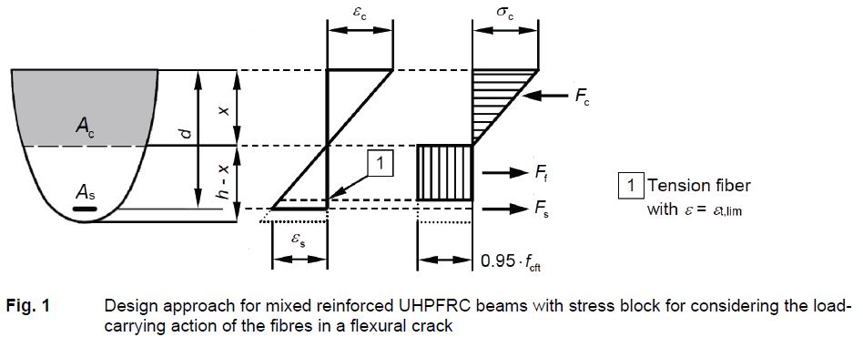
The ultimate strain εt,lim of the stress block is not a fixed value, but refers to a crack width wlim which shall be deemed as "critical" when being reached at the extreme tension fibre of the cross-section. Reaching wlim marks the ultimate contribution of the fibres in the flexural crack in case of cross-sections exclusively reinforced with steel fibres and the beginning of strain localisation in case of cross-sections with mixed reinforcement. With mixed reinforced cross-sections, strain localisation is a further possible failure mode in addition to the well-known failure modes flexural tensile failure and flexural compression failure. It was observed in several experiments on mixed reinforced beams made of normal-strength concrete (NSC), high-strength concrete (HSC) and UHPFRC.
Based on the evaluation of typical stress-crack opening relationships and observations from three-point bending tests, wlim = 0.4 mm is suggested for UHPFRC reinforced with micro steel fibres – independent of the fibre geometry and the fibre volume fraction. In general, the "critical" crack width can be derived for any steel fibre reinforced concrete – regardless of strength – from the crack width or the deflection at which the residual flexural tensile strength reaches its maximum in the three-point bending test. In this way, the scope of application of the verification method can easily be extended to NSC and HSC reinforced with macrofibres.
The crack width is divided by a structural characteristic length lcs to convert it into strain. In case of a single flexural crack, the crack width is mainly affected by the deformation within the discontinuity region on either side of the crack (Saint-Venant’s Problem). In this case, the characteristic length lcs is defined based on the work of König and Fehling who analysed the plane stress and strain state within the discontinuity region. In case of stabilised cracking, the structural characteristic length is equated with the crack spacing, which depends on the reinforcement ratio related to the effective tension area and on the diameter of reinforcing bar. The characteristic length defined in this way can represent a value of 0 < lcs ≤ 0.75 h. The ultimate strain εt,lim of the stress block results in:
In Eq. (1), wlim = 0.4 mm is the "critical" crack width, ρs,eff = As1/Ac,eff is the reinforcement ratio related to the effective tension area, αcf is a coefficient taking account of long term effects on the post-cracking tensile strength, and Φs is the diameter of reinforcing bar. The larger value of εt,lim resulting from either Eq. (1a) (derived from the deformation within the discontinuity region of a single flexural crack) or Eq. (1b) (derived from the crack spacing) is the governing value.
While the strain at the extreme tension fibre of the cross-section is less than εt,lim, the stress block is applied to the entire tension zone. Otherwise, the stress block is only applied up to the section fibre marked with "1" in Fig. 1, which just reaches the ultimate strain εt,lim. The location of the section fibre "1" depends on the particular strain distribution. The resulting moment resistance typically decreases when the strain at the extreme tension fibre of the cross-section exceeds εt,lim. This means that εt,lim is a decisive parameter with regard to the onset of strain localisation.
Parameter study and validation of the verification method
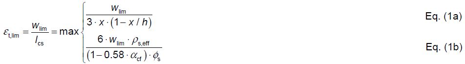
For illustrating the dependencies, εt,lim was evaluated as function of the section depth and the ratio of longitudinal reinforcement by means of design values. Two different post-cracking tensile strengths as well as two different diameters of reinforcing bar were applied. UHPFRC of strength class C150/165 with fcd = 85 MPa and reinforcing steel B500 with fyd = 435 MPa and bilinear stress-strain relation with horizontal top branch was assumed for all calculations. The abscissa of the diagrams in Fig. 2 shows the ratio of longitudinal reinforcement ρl = As/(b·d) and the ordinate shows the ultimate strain εt,lim. The coloured curves represent the results for different section depths h. The ratio of longitudinal reinforcement, for which crushing of the concrete compression zone becomes the governing failure mode, is marked with "C". Strain localisation is no longer relevant for ratios of longitudinal reinforcement higher than the one at point "C". The curves which develop approximately linearly from the origin of the graphs in Fig. 2 result from Eq. (1b). They are almost unaffected by the section depth. Each curve diverging therefrom to the left represents a specific section depth. These curves result from Eq. (1a), which is governing especially for small section depths and low reinforcement ratios. According to Eq. (1a), εt,lim is independent of the diameter of the reinforcing bar, but it strongly depends on the design value the post-cracking tensile strength fcftd. Since the diameter of reinforcing bar Φs significantly influences the crack spacing, the ultimate strain εt,lim obtained from Eq. (1b) considerably differs in the left and right diagrams in Fig. 2.
To validate the verification method, test data from 228 UHPFRC beams were arranged in a UHPFRC flexural database. Different shapes of cross-section (compact cross-section, I-section, T-section) and reinforcement configurations were considered, including prestressed, exclusively fibre reinforced, and exclusively rebar reinforced members. Different methods of material characterisation, execution, and documentation of experiments as well as partially missing or unclear information required a careful evaluation of each dataset and – where necessary – standardisation or complement of the data before being included in the database.
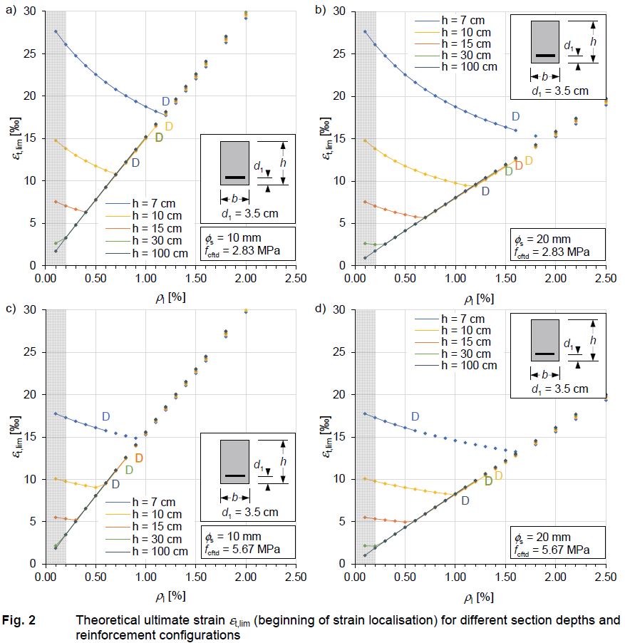
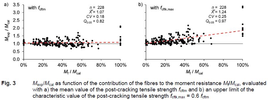
The comparison of the experiment and the verification procedure is carried out by relating the experimentally determined moment resistance Mexp (= maximum bending moment in the test) and the theoretical moment resistance Mcal determined by means of the model according to Section 2. Evaluation was performed with the mean values of the material parameters and without consideration of partial safety factors. Figure 3a shows Mexp/Mcal as function of the contribution of the fibres to the theoretical moment resistance Mf/Mcal. The regression line shows that Mf/Mcal only slightly influences the ratio Mexp/Mcal confirming overall good model prediction accuracy (Mexp/Mcal ≈ 1.0). However, the scatter of Mexp/Mcal increases with increasing fibre contribution Mf/Mcal, since the post-cracking tensile strength shows a wider spread than other geometric and material parameters. In order to guarantee the reliability level demanded by Eurocode 0, a further evaluation was performed applying an upper limit of the characteristic value of the post-cracking tensile strength fcftk,max = 0.6 fcftm instead of the mean value of the post-cracking tensile strength fcftm (Fig. 3b). fcftk,max is based on the draft of the forthcoming Eurocode 2. The regression line in Fig. 3b indicates that now Mexp/Mcal increases on average as the fibre contribution Mf/Mcal increases. At the same time, unsafe results with Mexp/Mcal < 1.0 are avoided to a large extend. This results in acceptable 5 % quantiles of the ratio Mexp/Mcal of Q0.05 = 1.00 for members with compact cross-section, Q0.05 = 0.99 for members with I-section, Q0.05 = 0.90 for members with T-section, and Q0.05 = 0.97 for the universe of the 228 data sets.
Summary of the results and conclusions
The comparison with well-documented experiments from Stürwald shows that the ultimate moment resistance, the moment-curvature relationship, and the failure mode are predicted quite accurately by the proposed verification method. A sensitivity study shows basic relationships that could also be observed in experiments.
A parameter study performed by means of design values illustrates the influence of different geometric and material parameters on the ultimate strain εt,lim and the onset of strain localisation respectively. Strain localisation initiates earlier with large section depths showing low ratio of longitudinal reinforce-ment and large diameter of reinforcing bar than with thin section depths. The latter show very large curvature and ultimate strain εt,lim until reaching the ultimate moment resistance – independent of the ratio of longitudinal reinforcement. With higher ratio of longitudinal reinforcement, flexural compression failure occurs before the onset of strain localisation.
When evaluating the verification method with the mean values of the material parameters, the model agrees well with the experimental results for the data sets of the UHPFRC flexural database. The ratio Mexp/Mcal is on average X̅ = 1.09 for the 177 beams with compact cross-section, X̅ = 1.01 for the 31 beams with I-section, and X̅ = 0.94 for the 20 beams with T-section. The coefficient of variation CV is 0.19, 0.13, and 0.11 for the three types of cross-section. X̅ = 1.07 and CV = 0.18 are obtained for the universe of the 228 data sets of the UHPFRC flexural database. An acceptable safety level is achieved by limiting the characteristic value of the post-cracking tensile strength to 0.6 times the mean value.
The longitudinal reinforcement and stirrups in the tension zone reduce the fibre reinforced concrete area effective in tension. However, the evaluation of Mexp/Mcal as function of the reduction of the concrete area caused by the longitudinal reinforcement and stirrups makes it appear justifiable to determine the force Ff resulting from the contribution of UHPFRC in tension in a simplified way by means of the gross fibre reinforced concrete tensile area Acf, i.e. without reducing Acf by the cross-sectional area of the longitudinal reinforcement and the area of the stirrup bars.
Since the ultimate strain εt,lim depends – among other things – on the ratio of longitudinal reinforcement, evaluating the verification procedure results in an extended iterative process, which requires the use of an equation solver (non-linear system of equations). A simplification can be achieved by assuming a conservative value of the ultimate strain. In this respect, εt,lim = 5 ‰ represents a safe approach for 187 of the 191 mixed reinforced members of the UHPFRC flexural database as well as for the exclusively fibre reinforced members with section depths not larger than approximately 150 mm. Only for four mixed reinforced members with large section depth and small ratio of longitudinal reinforcement, the approach εt,lim = 5 ‰ = const. has a negative impact on the model safety.
Based on the results of the validation, the verification procedure can be recommended for use in the DAfStb Guideline "Ultra-High-Performance Concrete".
Due to the mechanical basis of the proposed verification method, its application is not limited to UHPFRC. The most relevant parameter is the "critical" crack width, which can be derived from the load-deflection or load-CMOD curve (CMOD = Crack Mouth Opening Displacement) of the three-point bending test. By adapting the "critical" crack width, the verification method can easily be extended to steel fibre reinforced concrete with macrofibres. Such an extension is intended for the future and may accompany the work on the new DAfStb Guideline "Steel Fibre Reinforced Concrete" based on the forthcoming Eurocode 2. To support this work, an NSC-HSC flexural database was compiled from test data from 224 beams made of NSC and HSC. The adaptability of the proposed verification method has already been demonstrated by means of two data sets from this database.
Publications
LEUTBECHER, T.; METJE, K., 2024. Flexural design of ultra-high-performance fiber-reinforced concrete girders | Biegebemessung von Biegeträgern aus stahlfaserverstärktem ultrahochfestem Beton. In: Kongressunterlagen 68. BetonTage: Transformation gestalten. Ulm, 14.-16. Mai 2024. Betonwerk und Fertigteil-Technik/Concrete Plant and Precast Technology. 90(5), 113. ISSN 0373-4331
METJE, K.; LEUTBECHER, T., 2023. Die UHFB-Biegedatenbank - Validierung eines Bemessungsansatzes für Biegung mit oder ohne Längskraft. Beton- und Stahlbetonbau. 118(12), 864-878. doi:10.1002/best.202300070
Supporting Information: Data S1. UHFB Biegedatenbank
LEUTBECHER, T.; HECK, L.; METJE, K.; RIEDEL, P., 2023. Predicting the moment resistance and localization strain of reinforced UHPFRC cross-sections subjected to bending. Engineering Structures. 293, 116607. doi:10.1016/j.engstruct.2023.116607
LEUTBECHER, T.; HECK, L.; METJE, K.; RIEDEL, P., 2022. Zur Biegebemessung kombiniert bewehrter UHFB-Biegeträger. Beton- und Stahlbetonbau. 117(11), 863-877. doi:10.1002/best.202200077